About CAD layers
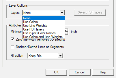
When DWG and DXF files become PDF files, they keep their layers as long as the settings are correct. When converting back to CAD, pdf2cad looks at attributes in the PDF file to generate layers. It gathers all objects meeting the chosen attribute criteria and puts them on one layer. If the PDF file has three colors, the resulting DXF file will have three layers. This makes it easy to turn sections of a drawing on or off for easier editing and viewing.
Frequent Questions About CAD Layers
What are CAD layers used for?
Layers separate different parts of a CAD file to make working on the file easier. They isolate logical sections for modification. This allows changes without unintended changes to overlapping and nearby elements. In a building plan, layers might include the floor plan, electrical, plumbing and more. To make working easier, you can lock, hide and fade these layers.
How can layers be identified?
There are many ways to arrange layers. The most common is by color. In the building plan example above, the floor plan could be yellow, the doors red and the electrical blue. Layers can also separate based on line weight, spot color and other definitions in the source PDF. pdf2cad supports layer separation based on all these factors as well combinations. AutoCAD offers a good overview About Layers.


Are there standards for naming CAD layers?
Standards exist to ease sharing and exchange of CAD drawings and data. The United States National CAD Standard (NCS) offers conventions for naming and organizing layers. Read more about the NCS Layer Name Format Standards. These follow ISO 13567, the published international standard for structuring layers
Example: The complete NCS layer name format showing Discipline Designator, the Major Group, two Minor Groups and the Status Field.
.
Example: The complete NCS layer name format showing Discipline Designator, the Major Group, two Minor Groups and the Status Field.
.

