PDF Conversion Options – PDF to Vector Formats

PDF Conversion Options

Below is a summary of all vector PDF conversion options available in pdf2cad, pdf2picture and PDF FLY. These options and more are also available to developers via the PDF Conversion SDK/API or command line tools.

Conversion options - general settings

General Settings Tab

  • Characters as Strings Combines characters into words, and words into text strings, based on context.
  • Convert Characters to CurvesCreates a visual graphic match for text defined with unknown or unavailable fonts.
  • Rotate: Rotates drawing any degree in either direction.
  • Scale Text: Enlarges or reduces the size of the text in the converted file.
  • Emulate PDF cropping: Cropping removes unnecessary outer areas of a drawing. PDF supports cropping but some vector formats (WMF, CGM, DXF, and HPGL) don’tWithout cropping, these formats would transfer unwanted elements during conversion. Activate ‘Emulate PDF cropping’ to ensue clean borders. Using this feature, the resulting file will match the original.PDF.
  • Show Font Warning: If the fonts in a PDF file are not installed on your computer, the text will not look right. Font mapping ensures the closest match possible. It also compensates for different font naming conventions across systems.
  • Ignore paths, text images: Turn certain elements on or off during conversion.
  • CAD Format: Choose your output format. DWG for AutoCAD, DXF for most engineering and technical programs, and HPGL for plotter-specific applications.
font mapping dialog

Font Mappings Tab

Text converts fine when PDF files use standard fonts. If text converts but doesn’t display right, you have a font mapping issue. Fonts are a tricky subject. Installed fonts differ from system to system. Sometimes, the same font may even go by different names. For a perfect conversion, the same font needs to be on the source and target system. License agreements protect font vendors from the illegal use of their typefaces. Embed only system fonts and permitted fonts. For more detail on font issues, read PDF Font Mapping When Converting Files and PDF Fonts: Embedding and Substitution from Adobe.

Document fonts display based on comparing the font name in the PDF file with the font name on your system. If the fonts on your PC match the PDF, the file will look perfect. Often, the font names don’t match and the text looks ‘off’. The first thing to check is whether you have a font name mismatch. Arial Bold, for example, may be “EHJPKB+Arial-Bold” in the original file. The same font is “Arial” on your PC. When you match the two, it’s known as “Font Mapping”. In this example, map “EHJPKB_Arial-Bold” to “Arial” with font style “Bold”. If you can’t make a successful match, we substitute the closest font. This is “Font Substitution” and is automatic.

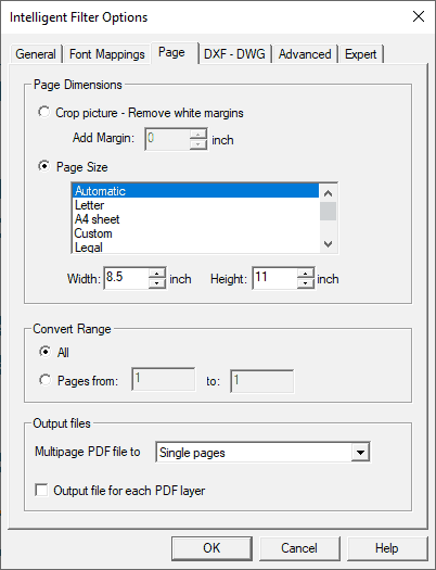
PDF conversion page options

Page Settings Tab

The Page Settings control options apply to all files. All of the other options vary depending on whether you choose a vector or bitmap output format.

Crop Picture: Remove Margin: By default, the margins of the PDF file are used. This setting can adjust or remove white space.

Page Size: pdf2cad will automatically figure out the page size. If you want to force a standard or custom page size, select it or enter dimensions.

Convert Range: pdf2cad, by default, will convert all pages of a file. You can set a page range if you only want selected pages.

Page Mapping: By default, a multi-page PDF file converts into a vector page for each PDF page. Other choices included include merging all pages into one file and applying horizontal or vertical alignment.

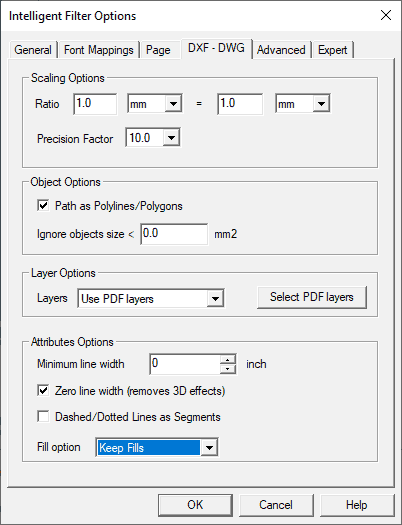
PDF to DWG DXF format specific options

DWG and DXF Format Specific Options

The PDF Conversion Options for DWG and DXF options apply to specific CAD drawing features.

Scaling Factor:  CAD programs define dimension in units. These units disappear when creating a PDF file but the scale remains. You can set a scaling factor for the x-y relationship during conversion. You can also set the units when you open the converted file in your CAD program. By default, pdf2cad uses 1mm (0,03937 inch) = 1 unit in the CAD output. To learn more about CAD units, read Units and Scales
Precision Factor: The default precision is set to 10. Sometimes, it will help increase coordinate accuracy to change this to 1 or to 100. If none of these settings provide desirable results, please send us the file to diagnose.
Paths as Polylines/Polygons: PDF doesn’t understand objects or their relationships. To compensate for this, use our object recognition engine. It identifies lines and curves and renders them as shapes. Polylines are a connected sequence of lines and arcs that create a single object. Polygons are shapes with straight sides.
Layers: By default, all objects are on one layer. You can separate layers by color, line width, PDF layers, spot colors, or a combination of color and line width.
Minimum line width: Defines the smallest line width for each vector object in mm. The default is 0.
Zero line width: Removes 3D effects
Dashed and Dotted lines as segments: PDF sees dashed and dotted lines as lots of individual lines. By selecting this feature, the lines will be converted into whole lines with a pattern.

Fill option: Sometimes, white fills in a PDF file show up as black fills in a DXF file. If this is a problem, use this option to ignore white fills.

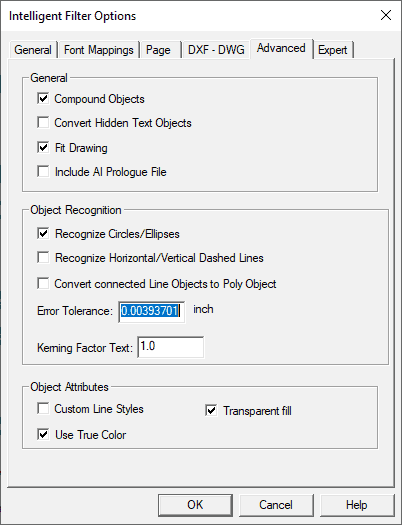
Advanced PDF Conversion Options

Advanced DXF and DWG Options

Recognize Circles/Ellipses: Our object recognition engine identifies closed polygons and circular paths. Convert them into circular and elliptical shapes.

Recognize Horizontal/Vertical Dashed Lines: Create one line object with a line-style attribute.
Error Tolerance: This is a tolerance level set for the recognition of CAD objects. If one point on the closed polyline is outside of the specified range, it will remain a polyline.
Kerning Factor: This setting controls the space between letters or characters. Apply a kerning factor to make the space between characters wider or more narrow. A factor of 1.2 would increase the space by 120%, Important Note! A spacing problem may not be a kerning issue at all. It may be due to a font mismatch and is best solved through font mapping.
Compound Objects: A compound object is a group of objects that make up a discreet item. The object recognition engine identifies objects to group into compound objects. If you want all graphics to remain as singular objects, turn this off.
Convert Hidden Text Objects: PDF files can have transparent text or text hidden under an object. This PDF Conversion Option converts all text on the page, including hidden text.
Fit Drawing: This option scales the converted PDF to be fully visible on the page when opened in a CAD program.
Include AI Prologue File: Early Adobe Illustrator files (v8 or earlier) need an AI prologue file to convert. Only use this option if needed. Starting with Illustrator version 9, the AI file is PDF compatible.
Custom Line Styles: Map line styles in the PDF to custom line styles in the CAD file.

Use True Color: Uses RGB true color values in the CAD file. By default, files use an indexed 256-color table. 

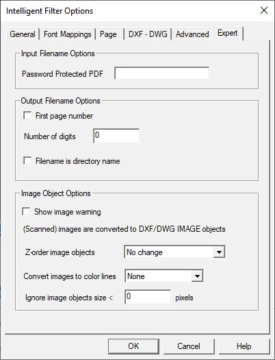
expert options

Expert CAD Options

Password Protected PDF. If the PDF file you are converting has a password, enter it here.

First Page Number. When unchecked, the first converted page will be the same as the file name. For example, page one of myfile.pdf becomes myfile.dxf. Checking this option adds a numeric suffix. In our myfile.pdf example, the first page comes out as myfile-1.dxf (followed by myfile-2.dxf, etc.).
Number of Digits. If you choose the ‘First Page Number’ option, enter the number of digits for the suffix. A value of 0 makes page 2 of myfile.dxf will come out as myfile-2.dxf; page 3 as myfile-3.dxf, etc. Setting this option to 4, will add a 4 digit suffix (myfile-0002.dxf). Using this feature ensures logical alphanumeric listings in document management systems.
Filename is directory. When checked the file destination is a new directory. The directory is the chosen output name with no file extension. The converted files save to this directory using only their page number.
Show image warning. Check this option if you want alerts when the input file (PDF, EPS or AI) contains images. Images appear in the CAD output as non-editable IMAGE objects.
Z-Order Image Objects. Z-Order refers to the order of overlapping objects. The order in the PDF file is the default. You can place images at the back or reversed at the back of the drawing. This is useful when PDF images are transparent since IMAGE objects in DWG or DXF are opaque.
Convert cropped images to color lines. DWG and DXF don’t support image cropping. Using this option is useful with small cropped images. It converts them to color lines and crops them that way.

Ignore Image Objects Size Less Than. This option strips small image objects during conversion.